Turnout Tips"
By Gerry Hopkins MMR
Turnouts are the least understood of the items associated with model railways and to compound the problem upgrading to DCC has brought more misunderstanding. There are many very good web pages on all the variations of the the different brands so I will only give a few of the basic tips with the help of detailed photos.
The term DCC Friendly means many things to many people, There are two main points of view - the powered frog and the dead frog.
The powered frog has its electrical polarity changed to match the route through the frog, this can be done by the contact of the moving point rail against the fixed stock rail. The alternative is to use the contacts on a separate switch; either a slide switch, micro switch or turnout motor.
The dead frog (sorry Kermit) is electrically isolated from the rest of the track. The benefits of this are ; no extra switches or contacts, no extra wiring, no climbing under the layout to fix or replace the extra parts,
Most modern (made in the past 15 years) locos have pick ups on all the wheels (The Italian brand is/was the exception) so passing over a 1" piece of dead rail is quite acceptable. My HOn30 locos are quite happy with dead frogs as are all the stadard gauge locos.
Below are a few of the common tips for electrical and mechanical problems to help getting your layout working.
CLICK ON ANY IMAGE TO ENLARGE
PECO
|
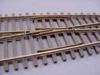
PECO FROG
This shows how I isolate the frog. I have not shown the styrene bits
glued into the gaps. At the top of the frog I have removed the short
pieces of rail and moved the rail section down. This removes a possible
alignment problem at a later date and means that no rail joiner /
fishplate is required.
|
 |
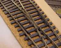
PECO CHECK GAUGE
While at the frog fit a piece of 15
thou (0.015") styrene to the check rails as shown. This will allow
wheels to NMRA standards to pass though the frog without the flange
hitting the frog and possibly derailing. The Insulfrog has a small
piece of plastic between the two frog rails to act as insulation - it
does the job very well - BUT - the wheel tread can bridge the gap. On
DC this has no short term effect but long term it will cause pitting in
the wheel. On DCC it will shut down the booster.
|
|
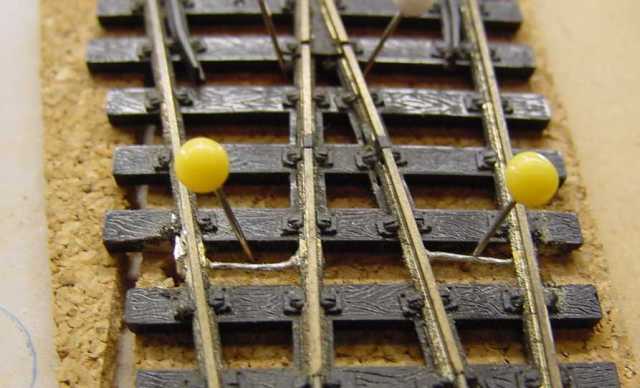
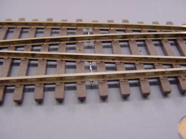
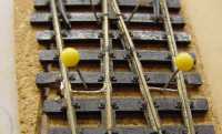
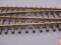
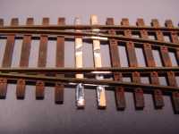
POINT RAIL
The turnout
relies on the contact of the point rail and stock rail to get power.
The yellow pins show a hard wire link between the two rails. This would
normally be below the ballast or under the layout but is shown here for
clarity. |
 |
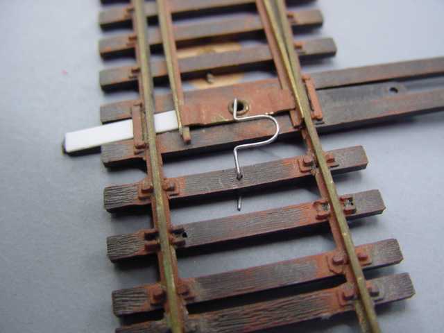
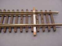
THROW BAR
This shows the throw bar with its positive locking spring (some times!!). The T bar to
the left has a tendency to move away from the throw bar thus reducing
the tension on the lock. This happens normally 33 days after you lay
the turnout. The white pin shows the correct alignment for the T piece.
I drill a small hole and insert a piece of wire as show. The wire is
normally cut level but I have bent it over so that you can see it. If
there is not enough tension on the spring the point rail can sit away
from the stock rail and cause derailments. |
 |
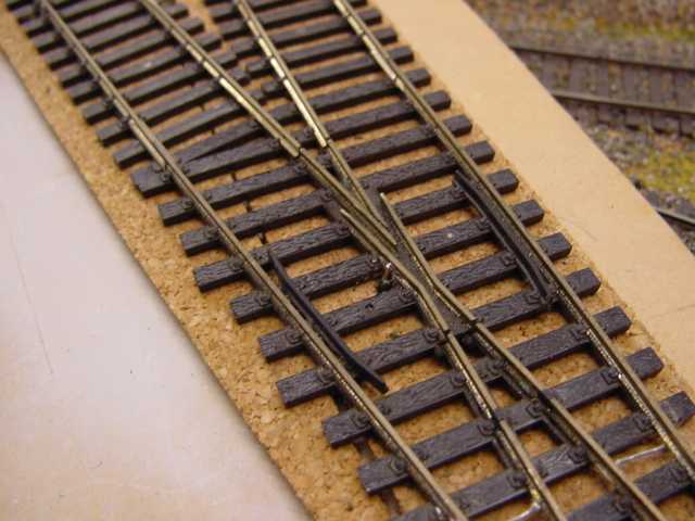
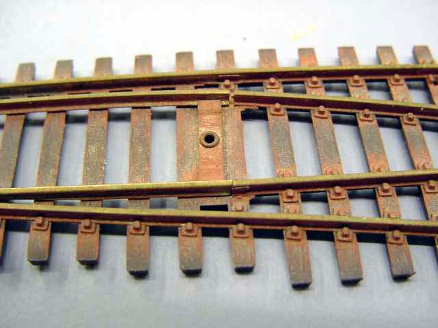
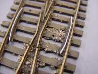
FROG ISOLATION
The frog is a casting on this turnout. It is easy to cut the joint between the rail
and the casting. It is not so easy to solder a wire to the frog.
|
|
POINT RAIL The stock rail can be wired to the
point rail as shown. The contact between the rails is very poor. |
|
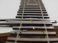
THROW BAR
The throw bar has been replaced with a PC board tie from Clover House.
The styrene is just cosmetic. |
|
OVER CENTRE
SPRING (OVER CENTER SPRING for USA)
A small piece if
spring wire - 0.010 " - has been inserted on the underside of the throw
bar for positive locking. The clear styrene is to stop the spring
dropping down. |
Shin O'Hara
|
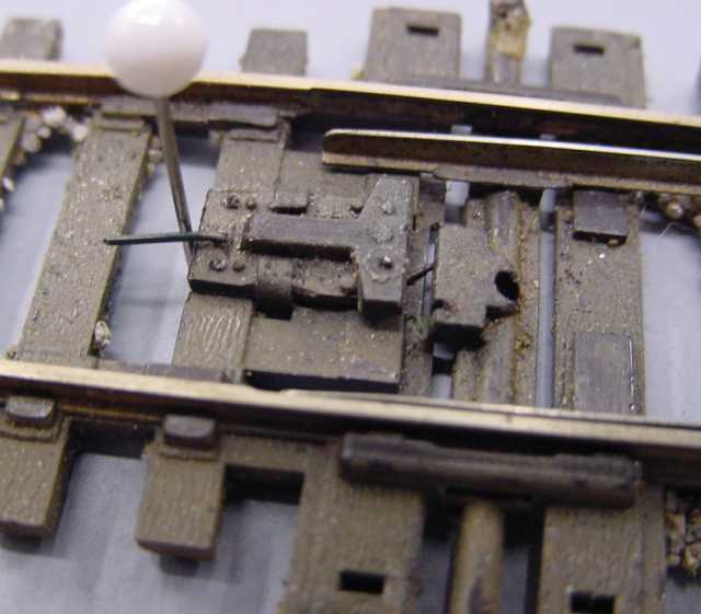
THROW BAR (Part One)
This view shows the
underside of the throw bar. As you can see there is a rivet in the
middle that holds the plastic to the metal bar between the point rails.
This plastic is very thin and after a period of time ( normally just
after you start wearing glasses) the plastic bends up in the middle.
Assuming all your wheels are set to NMRA standards the fact that the
two point rails are electrically joined should not cause problems, BUT,
the bending of the plastic allows the point rails to rise , as much as
1.5mm (0.060") . the rail can touch the underside of the locos or loco
pickups and cause a short. Of cause, the rail rising will also cause
derailments.
|
|
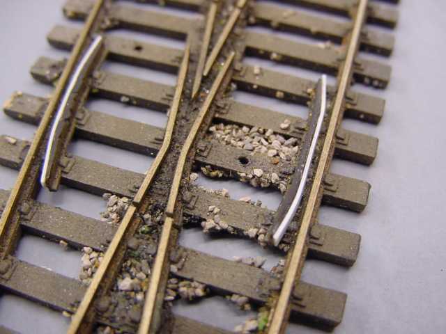
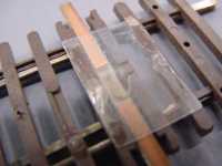
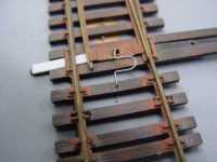
THROW BAR (Part Two)
This is the top
side, if the turnout has already been fitted to the layout , a short
term fix is to place a piece of 0.015" styrene as shown - you
will need a piece for each rail. The best fix is to replace the plastic
with a PC board tie before fitting the turnout.
You can also see the centreing (centering for US) spring for positive
locking.
|
|
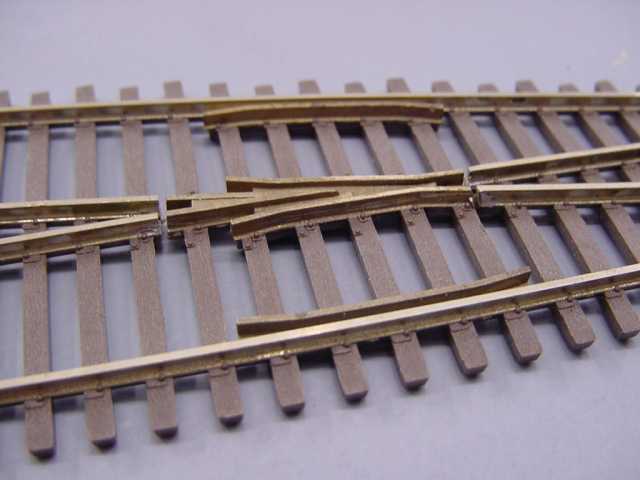
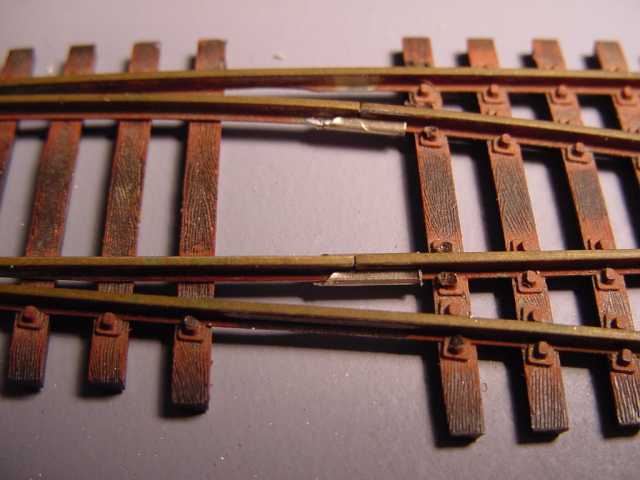
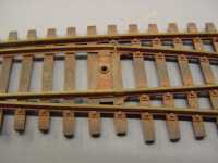
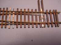
POINT RAIL PIVOT
Here is the the
major hurdle for most people wanting to "fix" the Shin O'Hara turnout,
but, it is not a hard fix. Remove the two ties under the pivot and
remove the metal bar between the two rails. Replace the two ties with
two pieces of PC board tie. Join the point rail to the fixed rail with
HALF a rail joiner. |

|
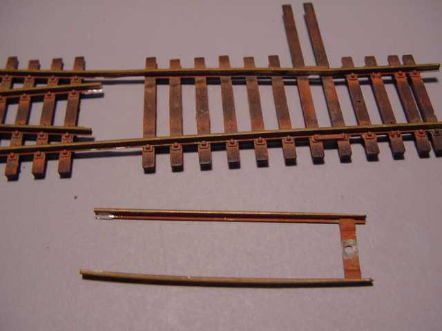
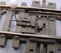
DISASSEMBLY
The point blades have
been removed and the plastic ties removed.
|
|
FITTING RAIL JOINERS
The rail joiner/fishplate was cut in half and then slid onto the fixed rail.
|
 |
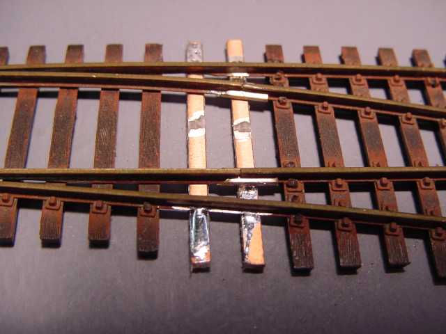
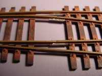
REPLACE THE TIES
Printed Circuit Board ties have been soldered into place. An insulation gap has been
cut into the centre. |
|
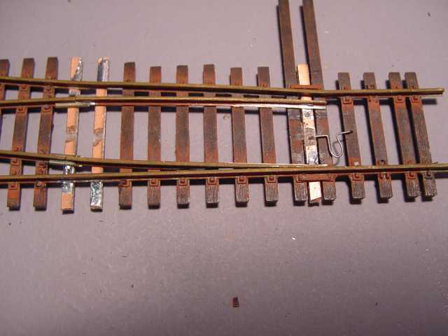
REPLACED THROW BAR The throw bar has also
been replaced with PCB ties stock. The centreing spring has been fitted
to make a more positive action of the throwbar.
|
ALL
TURNOUTS
|
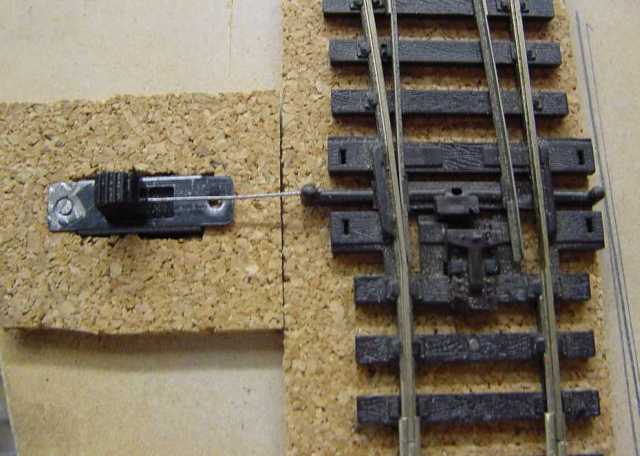
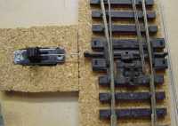
POSITIVE SWITCHING
This shows a
positive method of mechanical and electrical switching at low cost. The
method can be used on any brand of switch and gives a positive locking
of the throw bar, electrical switching of the frog, and spare contacts
for signaling. |
|
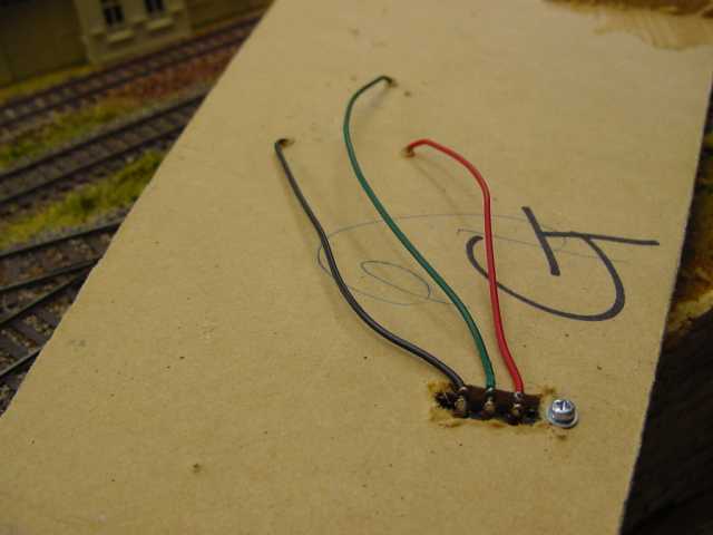
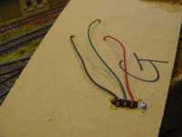
WIRING
The two stock rails (red
and black) and the frog (obviously green) can be wired back to the
switch. For those with an extra level of paranoia, cut the green wire
in the middle and connect a lamp (1152) between the frog and the switch.
|
|
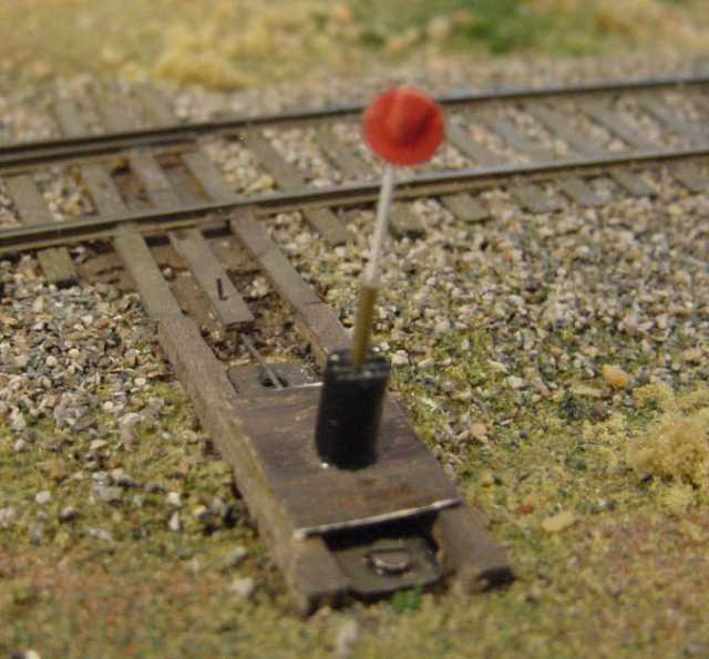
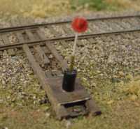
MAKE IT PRETTY The top of the slide
switch can be made to look like a switch stand with very little effort.
The slide switch would cost around a $1.00 each which is a
little less than the cost of a turnout motor, switch for the turnout
motor, wiring for the turnout motor, and a power source for the turnout
motor.
|
|
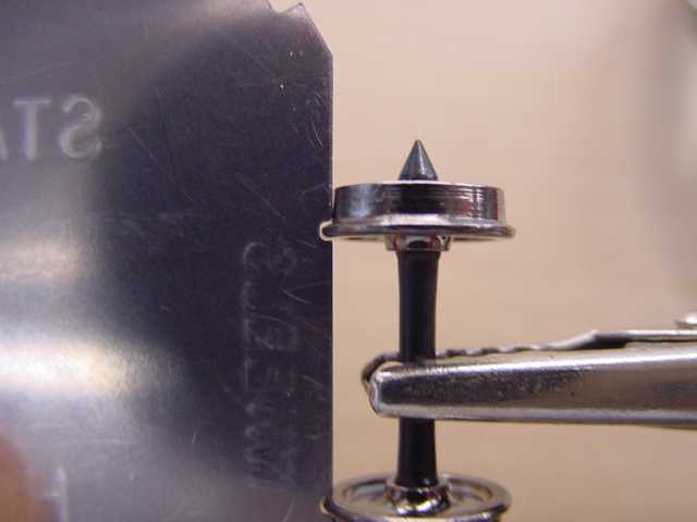
WHEELS IN GAUGE
This view shows my interpretaion of a "wheel set" in gauge and having the right
profile.
There should be light all around the flange and there should be a taper
on the wheel tread. The wheel set shown is a Proto 2000 item and
the gauge is an NMRA HO gauge. The same applies to all other gauges.
90% of turnout problems relate to wheels being out of gauge. The light
around the wheel lets you know that the wheel is not geing forced into
the gauge. The axles are often made of nylon so the axle can flex to
get the wheel into th gauge. Always be gentle.
|